
CATS User Manual
Last updated: 18 September 2026
Glossary
- Apogee
- The highest point of the rocket during a parabolic flight
- Barometer
- A sensor that measures ambient barometric pressure
- Calibrating
- A flight state in which the flight computer is in safe mode and performs no actions
- CLI
- Command Line Interface, used to read and change flight-computer values without the Configurator
- CRC
- Cyclic Redundancy Check, used to verify that received data is not corrupted
- Drogue Chute
- A relatively small parachute deployed at apogee to stabilize and slow the rocket during descent
- FHSS
- Frequency Hopping Spread Spectrum, a protocol that transmits telemetry data across multiple carrier frequencies
- FreeRTOS
- An operating system for embedded CPUs and the backbone of the CATS software
- FSM
- Finite State Machine, a model that describes the flight phases, how transitions between them occur, and which transitions are permitted
- GNSS
- Global Navigation Satellite System, such as GPS or Galileo
- I/O
- Input/Output, a collective term for the system’s inputs and outputs
- IMU
- Inertial Measurement Unit, a sensor that measures linear acceleration and angular velocity
- Kalman Filter
- A filtering technique used to estimate states according to physical laws and measurements
- Liftoff
- The event that marks the start of powered ascent
- Main Chute
- The larger parachute deployed at a specified height above ground level to slow the rocket before landing
- Patch Antenna
- A flat, highly directional antenna used by the CATS Vega to receive GNSS signals
- Power Supply
- A source of electrical power, typically a battery in a rocket
- PWM
- Pulse Width Modulation, a method used to control most modern servos
- Pyro
- A pyrotechnic charge initiated by applying current through two electrical leads
- Ready
- A flight state; when in this state, liftoff can be detected
- RF
- Radio Frequency
- Servo
- A small electric actuator whose position is controlled by a PWM signal
- Touchdown
- The final flight phase, entered when the rocket lands
- UART
- A serial communication interface used to exchange data between devices
Disclaimer
The use of the CATS System is at your own risk. The CATS System must always be used in conjunction with a second safety system that operates in a different manner, such as motor ejection or another electronic system, to ensure maximum safety.
The manufacturer is not liable for any damages that may occur as a result of using the CATS System, and will not be held responsible for any damages inflicted on third parties.
Do not touch the CATS Vega while it is powered through the battery port because high currents flow through the board.
The manufacturer cannot be held liable for any program errors or malfunctions in the software.
The hardware warranty covers manufacturing errors and defects in workmanship and materials for a period of two years from the date of purchase. This warranty does not cover damage caused by improper handling, accidents, or other external factors. In the event of a covered manufacturing error or defect, the manufacturer will repair or replace the hardware at no cost to the user. To make a claim under this warranty, the user must provide proof of purchase and report the issue to the manufacturer within the warranty period. The manufacturer reserves the right to inspect the hardware and determine the cause of any reported issue before providing a repair or replacement. This warranty is non-transferable and only applies to the original purchaser of the hardware.
Important Regulatory Information
FCC Part 15 Compliance
This equipment has been designed to operate in accordance with Part 15 of the FCC Rules for unlicensed radio frequency devices. To maintain cooperative use of the shared spectrum, operation should be subject to two general conditions: (1) the device should not cause harmful interference, and (2) it must accept any interference received, including interference that may cause undesired operation.
Intended Use and Operational Constraints
The CATS Vega and Ground Station are developed primarily for educational, professional, and experimental use within amateur High Power Rocketry. In the United States, rockets of this class are considered aircraft by the Federal Aviation Administration (CFR 14 §101.25). Operators should adhere to FAA and National Fire Protection Association (NFPA) safety codes, which typically require maintaining a safe distance of at least 1,500 feet from populated buildings or uninvolved persons. Due to the high-power radio frequency emissions in the 2.4 GHz band, users are strongly advised against operating this telemetry system in residential areas to prevent potential disruptions to local consumer networks.
Hardware Certification and Radio Frequency (RF) Operations
The system utilizes Semtech SX1280 RF modules operating in the 2.4 GHz Industrial, Scientific, and Medical (ISM) band. As this operates on a shared, unlicensed band, users are not protected against interference from other ambient RF sources. We have made good faith efforts to ensure the hardware design follows standard EMC practices; however, should your system cause interference with licensed radio systems or residential Wi-Fi networks, you are expected to power down the device until the interference issue is resolved.
European Union (EU) and CE Compliance Notice
For operation within the European Union (EU) and the European Economic Area (EEA), this equipment is subject to the Radio Equipment Directive (RED) 2014/53/EU. Users operating within the EU must configure the telemetry output via the CATS Configurator to comply with the ETSI EN 300 328 harmonized standard, which strictly limits 2.4 GHz wideband transmissions to a maximum of 100 mW (20 dBm) Equivalent Isotropic Radiated Power (EIRP).
Exception for Licensed Amateur Radio Operators: Users holding a valid amateur radio license are authorized to operate at higher power levels within the 2.4 GHz amateur allocation. Such operation must strictly adhere to national amateur radio regulations, including station identification rules and prohibitions on encrypted commercial data.
Environmental and Safety Declarations
This product is factory-assembled utilizing lead-free manufacturing processes with the intent of aligning with global Restriction on Hazardous Substances (RoHS) principles. Please practice responsible disposal at the end of the product’s life cycle by recycling it as electronic waste rather than disposing of it in standard household trash.
Introduction
Welcome to the CATS User Manual. The following pages explain the CATS System so that you can install, configure, test, fly, and recover a rocket using the CATS Vega flight computer and CATS Ground Station. Each component has a practical operating section, while later chapters provide additional technical detail.
If you have feedback, suggestions, or need further help, contact us on our Discord server. The CATS ecosystem is open source; source code and hardware designs are available on our GitHub page.
Coverage of This Manual
This manual covers the use of the CATS Vega flight computer and its Ground Station. It explains how the flight computer works, how to connect it to a Power Supply and deployment actuators, and how to configure it for your flight trajectory.
This manual does not cover everything that can be done with the CATS System. In particular, it does not explain how to modify the software or hardware, or how the software works in detail. For further information about those topics, contact us on our Discord server.
Module Overview
The CATS System has three main components.
CATS Vega: The flight computer installed inside your rocket.
Ground Station: The receiver that displays and records telemetry, supports recovery, and controls bench testing.
Configurator: The desktop application used to configure and update the CATS Vega, review a configuration before flight, manage profiles, and analyze completed flights.
Basic Functionality
This section provides a broad overview of the CATS System for users who are new to rocketry. The following sections explain each topic in greater detail.
The CATS Vega is the core of the system. Its main purpose is to deploy the drogue chute at Apogee and the main chute at a user-configurable height above ground level. To do this, it combines barometric and accelerometer data to estimate height above ground level and velocity.
The CATS System defines five events: Liftoff, Burnout, Apogee, Main Deployment, and Touchdown. The onboard control system triggers these events automatically, while the user defines the actions performed when each event occurs.
Up to eight actions can be assigned to each event. Actions include delays, pyro-channel and servo-channel triggers, and low-level I/O signals. This allows the user to define how the deployment mechanism is actuated. Most commercial recovery mechanisms use pyro or servo channels, and the CATS Vega provides two of each.
At the same time, the system transmits important data to the Ground Station, including GNSS data, current height, velocity, and flight state. The data is also recorded in onboard flash memory.
The Ground Station is also used for testing mode, in which the user can trigger configured events to test separation mechanisms.
CATS Vega
This section describes how the flight computer works and how to configure it for a flight. The How to Use section explains its basic features. For more detailed information, refer to Section 9.
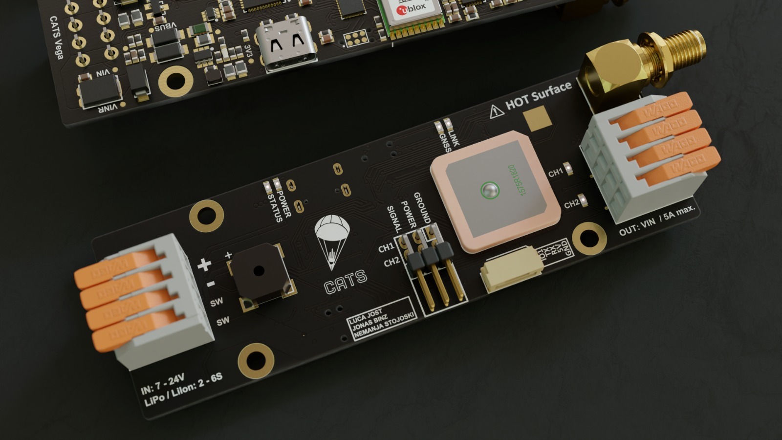
Hardware
Specifications
| Size | 100 × 33 × 15 mm (without the antenna) |
| Weight | 33 g |
| Input Voltage | 7 - 24 V |
| Power Consumption | 100 mA |
| Number of Pyro channels | 2 |
| Number of Servo channels | 2 |
| Number of IOs | 1 |
| Additional IO | UART |
| Servo Power | 5 V / 3 A max. |
| Microcontroller | STM32F4 |
| Flash Memory | 16MB |
| IMU | LSM6DSO32 |
| Barometer | MS5607 |
| Radio Frequency | ISM 2.4GHz |
| Radio Power | Up to 1W |
| Radio Range | Tested to 10km @100mW |
Hardware Overview
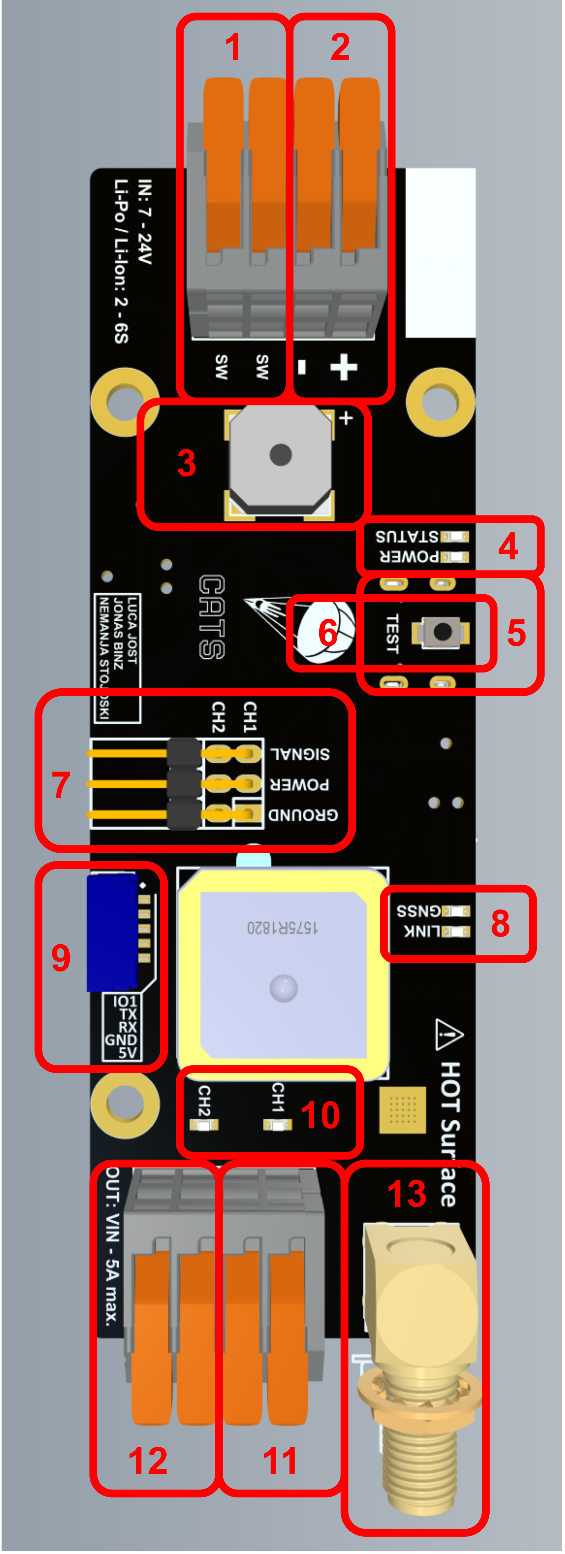
This section provides a quick hardware overview and shows the location of each port. The numbered markers in Figure 2 correspond to the following list.
Switch Port; Connect a manual switch between the two terminals.
Battery Port; Connect a battery to these terminals and observe the correct polarity.
Buzzer; Indicates flight-computer readiness and status through beeping patterns, as explained in Section 4.4.
Status LEDs; The POWER LED is illuminated when power is present. The STATUS LED blinks when the system is operating normally.
USB Connector; The connector is on the other side of the board.
Test Button; If this button is held during startup, the board enters testing mode if a testing phrase has been configured.
Servo Connector; This connector fits the standard servo connectors. Two servos can be connected to this connector.
Telemetry LEDs; The GNSS LED blinks whenever GNSS coordinates are received. The LINK LED blinks after a connection to the Ground Station has been established.
Low-Level I/O and UART Connector; Connect external hardware to this port to exchange data with the CATS board.
Pyro LEDs; These red LEDs are turned on when continuity of the Pyro channel is detected.
Pyro Channel 1; Connect a pyrotechnic charge or another supported device to this connector.
Pyro Channel 2; Connect a pyrotechnic charge or another supported device to this connector.
Antenna Connector; Connect an antenna here so that the CATS Vega can transmit data to the Ground Station.
Working Principle
This section briefly introduces the operating principles needed to understand the Vega flight computer’s configuration options.
Configurable Actions & Finite State Machine
The finite state machine (FSM), shown in Figure 3, controls the outputs of the Vega flight computer. When the flight computer is turned on, it starts in the Calibrating state. Every flight follows the sequence of states shown in Figure 3. Whenever a state transition occurs, the associated event is triggered.
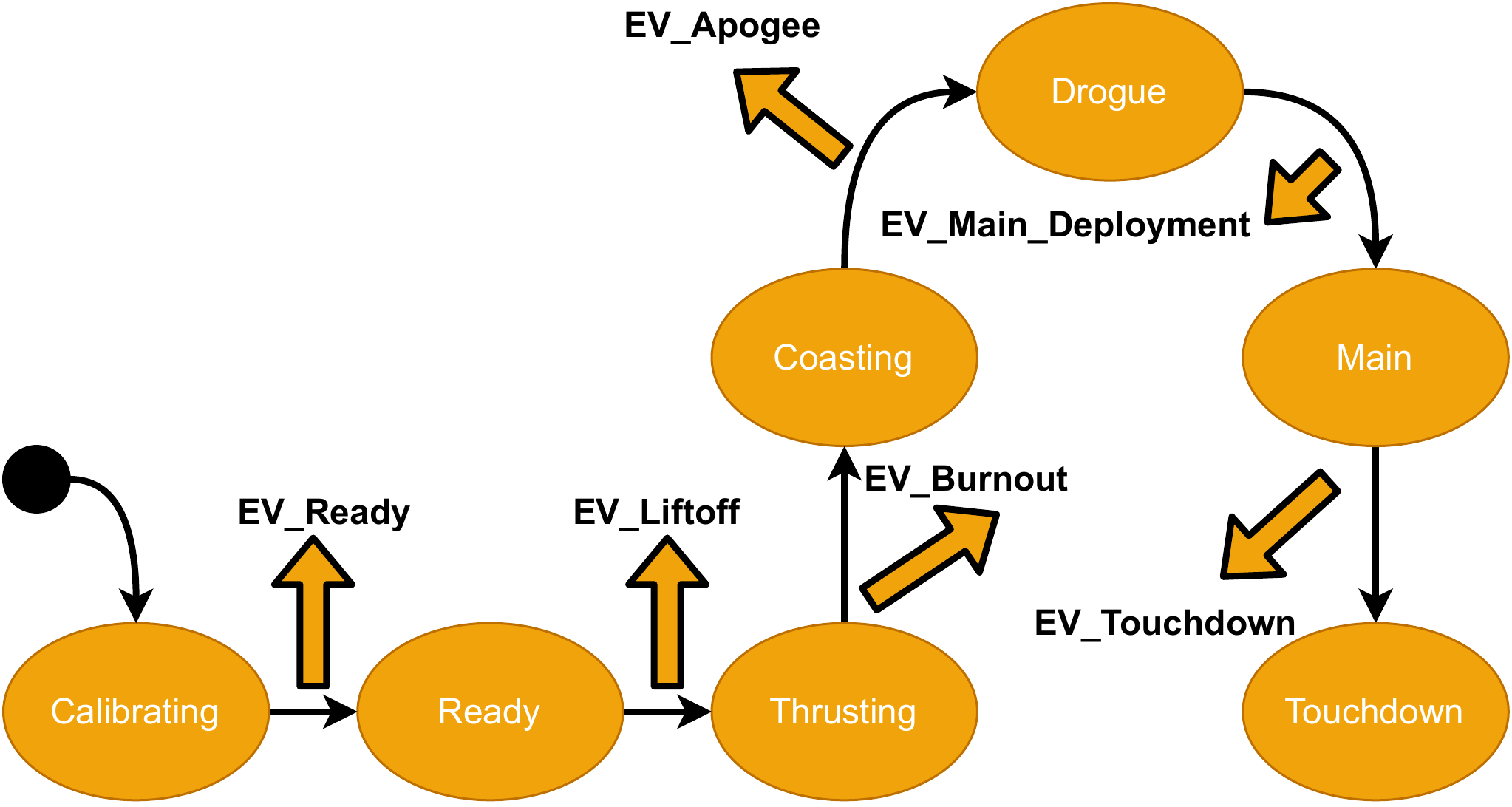
Each event can trigger one or more actions, such as a Pyro channel, Servo channel, or timer. Use the Configurator to assign actions to events, as described in Section 4.3.2.
| Calibrating Testing | A telemetry command starts testing mode. This transition is available only if testing mode was enabled through the Configurator. |
| Calibrating Ready | IMU (gyroscope and linear acceleration) readings are constant for 10 seconds. |
| Ready Thrusting | The measured acceleration in any direction exceeds the user-defined acceleration threshold for 0.1 seconds. |
| Thrusting Coasting | The measured acceleration in the “up” direction is smaller than 0 for 0.1 seconds |
| Coasting Drogue | The estimated velocity needs to be smaller than 0 for 0.3 seconds |
| Drogue Main | The estimated height is below the user-defined height for 0.3 seconds |
| Main Touchdown | The estimated velocity is in the bound for 1 second |
With this setup for state changes, the flight has a strictly controlled order. The Main event can only be thrown after the Apogee event. Events are also unique; during a flight only one event can be thrown.
Actions
When an event is triggered, the flight computer performs the actions assigned to it. Up to eight actions can be assigned to each event, supporting a wide range of applications. Examples include:
Enabling a camera at Liftoff using a Pyro channel,
Actuating a solenoid valve for two seconds using a Pyro channel,
Enabling some mechanism at engine burnout,
Disabling the camera at touchdown using the Pyro channel,
…
The full range of actions can be found below.
| Action | Parameter |
| Pyro 1 | ON/OFF |
| Pyro 2 | ON/OFF |
| Servo 1 | [0-1000]‰ |
| Servo 2 | [0-1000]‰ |
| Low-Level I/O | ON/OFF |
| Delay | [0-15000] ms |
| Recorder | ON/OFF/PREFILLING |
How actions can be configured is shown in section 7.
How to Use
Now that the hardware and software have been introduced, this section explains how to configure and mount the flight computer, update its software, and generate plots from flight data.
Connection to Your Computer
Before connecting your CATS Vega to your computer, download the Configurator from our releases page. Drivers are usually not required. If your computer does not recognize the device, refer to the troubleshooting steps in our wiki.
Description of the Configurator
The Configurator is the desktop application used to configure the CATS Vega, inspect its status, manage configuration profiles, run a preflight review, update firmware, and analyze flight logs. Download the latest release from the Configurator releases page.
When exactly one compatible Vega is connected, the Configurator selects it and connects automatically. If no automatic connection is made, use the device selector in the upper-right corner, choose the intended Vega, and select Connect. Use the refresh button if a newly connected device is not listed. When several Vegas are connected, always verify the selected device before changing or saving a configuration.
The left navigation provides the following work areas:
| Configuration | Flight settings, telemetry, testing, recorder settings, live board status, and hardware information. |
| Events & Timers | Actions assigned to flight events and the four configurable timers. |
| Profiles | Export the connected board configuration, compare another profile, and apply compatible settings. |
| Preflight | A read-only review of the configuration, warnings, event sequence, timers, and outputs. |
| CLI | Direct access to advanced flight-computer commands. |
| Flight Logs | Open local or onboard .cfl logs, generate plots, export data, or open a log in CATS Flights. |
| Firmware Updates | Detect supported devices, retrieve official releases, and install or prepare firmware. |
| Flights | Open CATS Flights in the default browser. |
Configuration
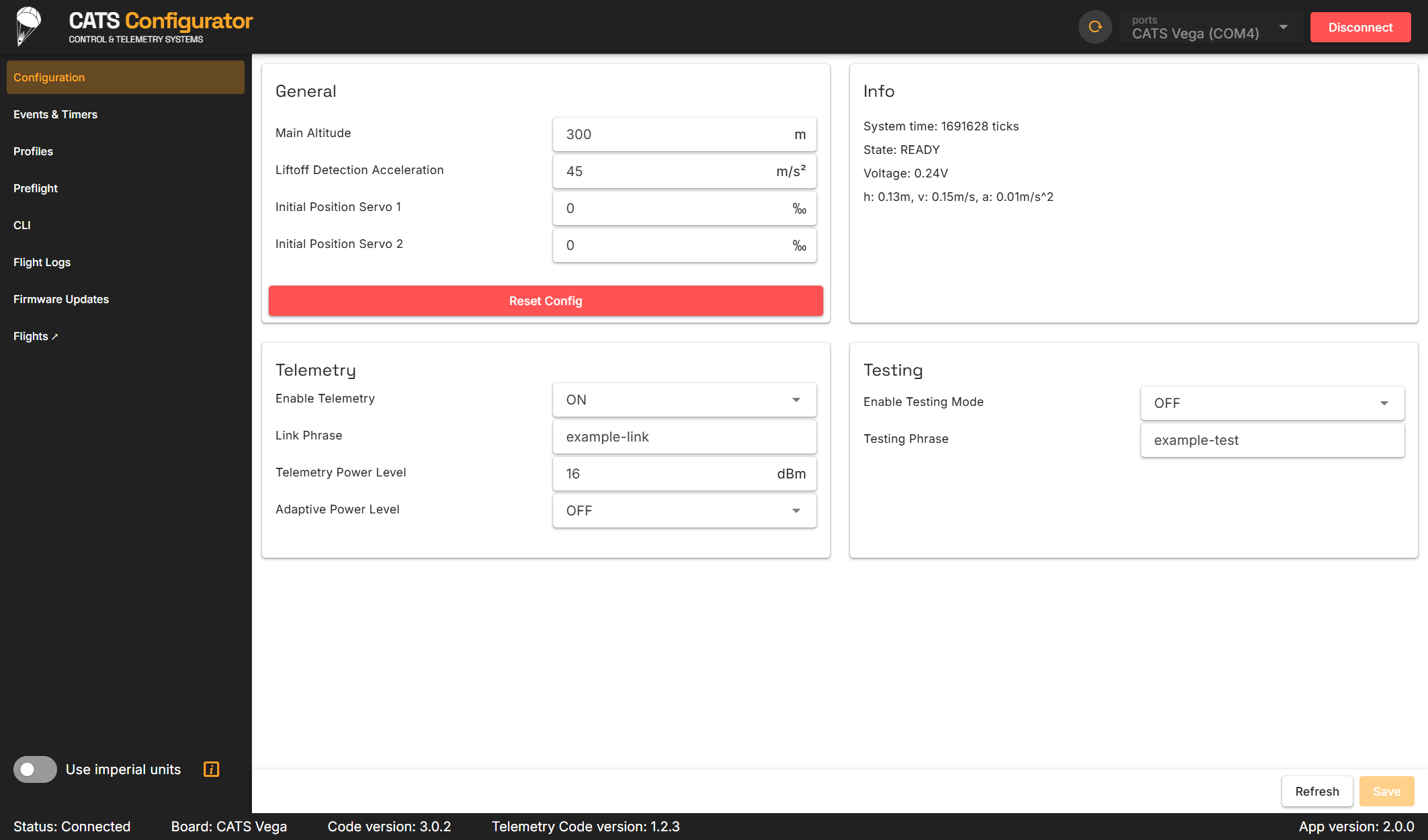
The Configuration page groups flight settings into General, Telemetry, Testing, Recording, Info, and Hardware Info panels. The General panel contains the main-deployment altitude, liftoff threshold, and initial servo positions. For most flights, use a liftoff threshold of 40 unless testing with the complete rocket shows that another value is required. The Telemetry and Testing panels contain the enable controls and phrases used by the Ground Station.
Changes shown in the Configurator are not persistent until Save is selected. Use Refresh to discard unsaved edits and reload the values stored on the Vega. Reset Config restores the default configuration after confirmation.
Events & Timers
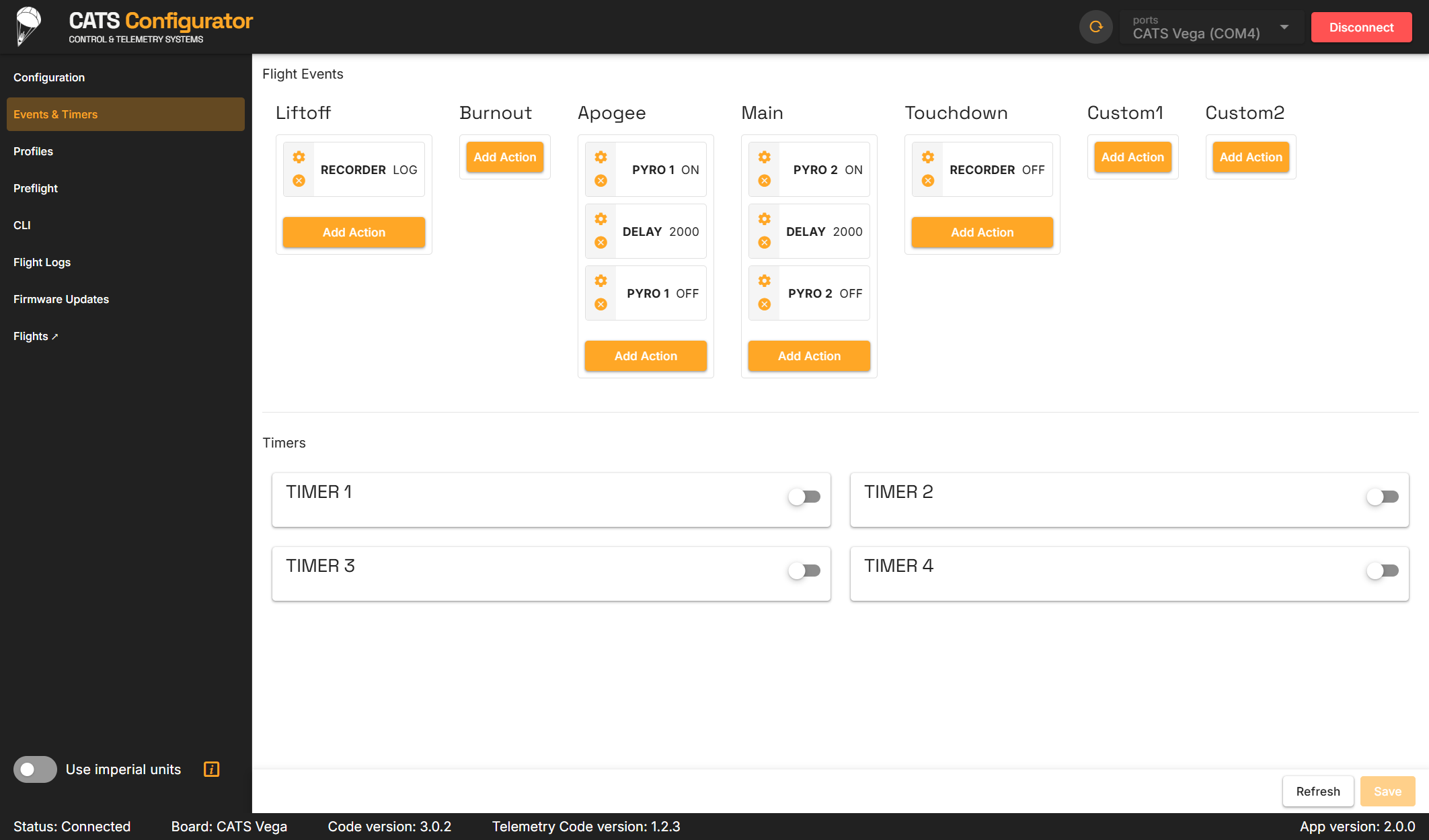
The Events & Timers page shows all flight events and their assigned actions, followed by the four timers. Select Add Action to add an output, recorder command, or delay to an event. Existing actions can be edited or removed. Up to eight actions can be assigned to each event. Select Save after changing events or timers.
Each timer has a start event, a duration, and an event to trigger when the duration expires. A timer can provide a backup event or trigger Custom 1 or Custom 2 for a payload sequence. Triggering an event through a timer does not force the flight-state estimator into the corresponding state.
Profiles
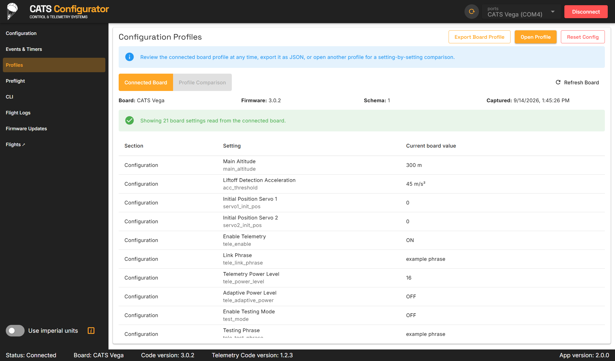
The Profiles page can export the complete connected-board configuration as a JSON profile. Opening another profile shows a setting-by-setting comparison with the connected Vega, including differences in configuration, events, timers, and recorder settings. Review compatibility warnings before applying a profile. You can apply the full compatible profile or individual differing settings, then save the resulting configuration to the board.
Preflight
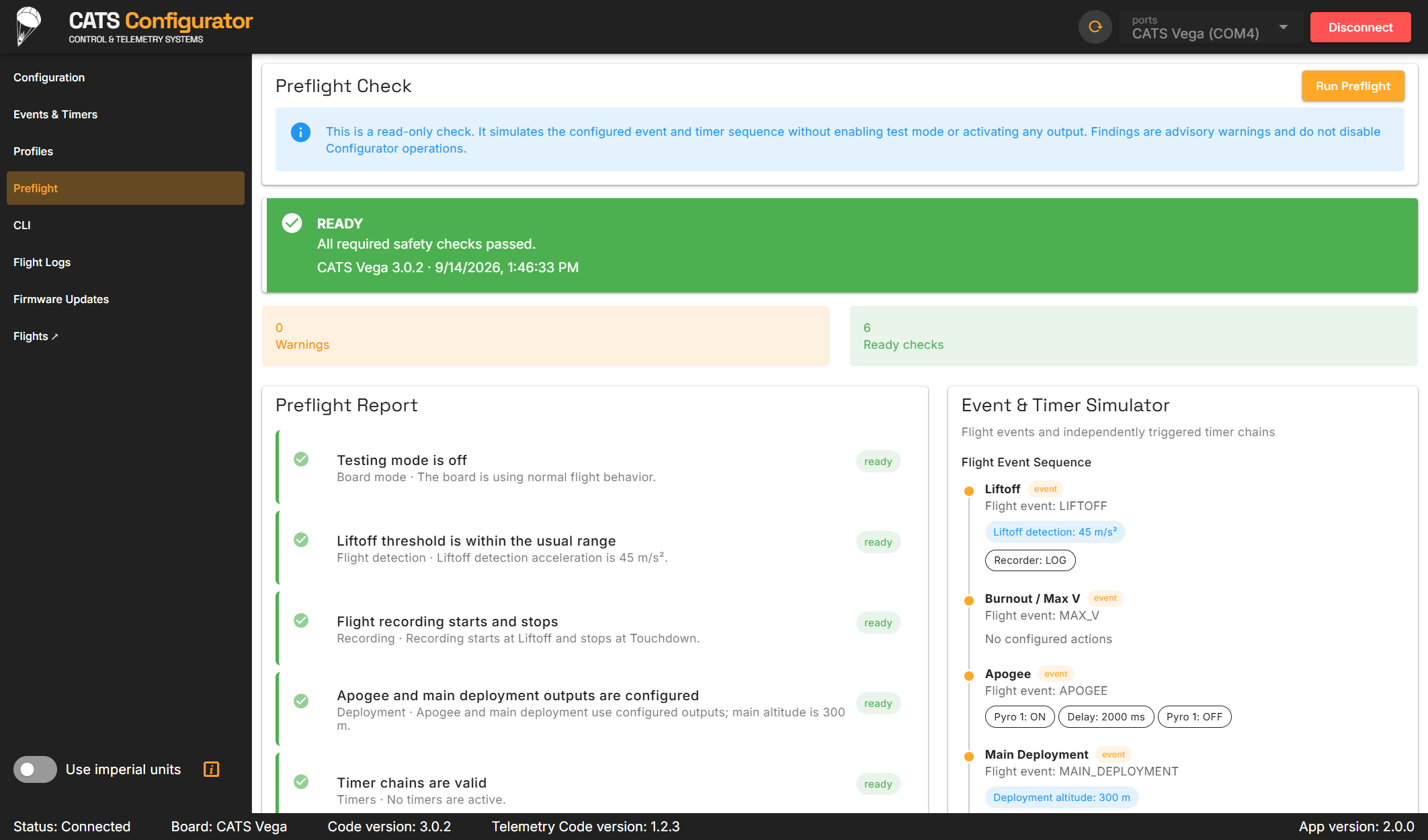
The Preflight page reads the saved board configuration and produces a report without changing it. Run Preflight after saving the final configuration. Review every error and warning, especially testing mode, telemetry and recording status, deployment actions, liftoff threshold, timer cycles, and event ordering. The event timeline summarizes which actions run at each flight event and which active timers may trigger additional events.
Preflight is an additional configuration review, not a substitute for continuity checks, deployment-system testing, range procedures, or a redundant recovery system.
CLI
The CLI page sends commands directly to the connected Vega. It is intended for advanced inspection and troubleshooting; normal configuration should be performed through the other pages. Common commands are listed in Section 9.5.
Flight Logs
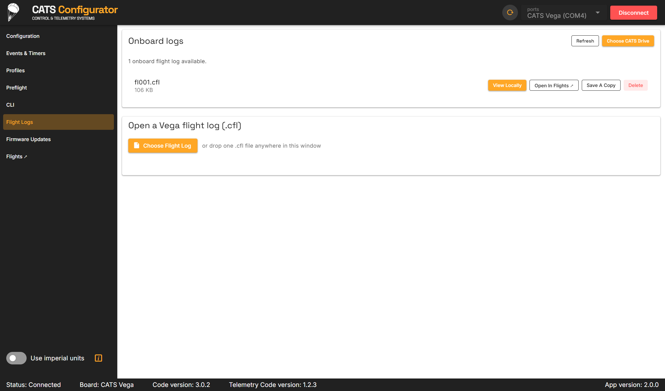
The Flight Logs page accepts one Vega .cfl file selected through the file picker or dropped anywhere in the Configurator window. When a Vega USB drive is mounted, the page also lists its onboard logs. An onboard log can be viewed locally, saved as a copy, deleted from the Vega, or opened in CATS Flights.
After opening a log, use Export CSV for tabular data or Export HTML for interactive plots. Open in Flights hands the selected log to CATS Flights through the local browser; the log remains on the computer unless it is explicitly saved or shared there.
Mounting
The CATS Vega does not require a specific mounting orientation. The system automatically detects the gravity vector for internal state estimation, so you can mount the board in any orientation.
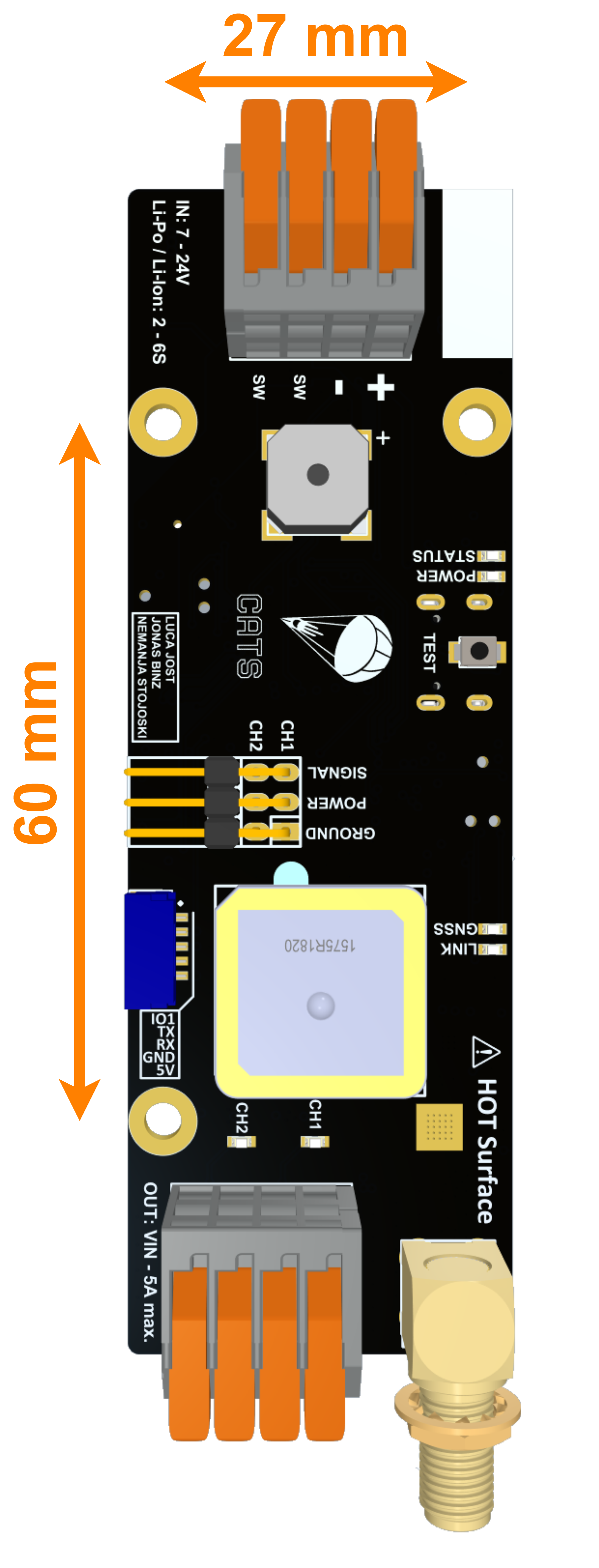
The board has a length of 100 mm, a width of 33 mm and a total height of 15 mm. Three mounting holes secure the system to the rocket. The mounting holes are spaced 60 mm by 27 mm and are designed for M3 screws. Use spacers to prevent the electronics from touching the rocket. Download the system’s 3D files from our GitHub repository.
For reliable radio reception during flight, pay close attention to the area surrounding each antenna. Install the CATS flight computer in a radio-transparent section of the rocket, such as fiberglass or cardboard. Do not install it in a carbon-fiber section, which blocks RF signals. Ensure that the onboard Patch Antenna has a clear view of the sky for optimal GNSS reception, and keep the telemetry antenna away from metal objects.
After power-up, the system detects the up direction once it is stable. A beeping pattern and the Ground Station indicate when the flight computer enters the Ready state. In this state, the flight computer is armed and waiting for Liftoff. Do not move the rocket, and follow all safety guidelines. At this stage, the flight computer can be disarmed only by switching it off. For more information about calibration, refer to Sections 9.3 and 4.2.1.
Battery, Switch and Actuators
The CATS Vega has one battery port, one switch port, two Pyro channels, two Servo channels, and one low-level I/O. The following sections briefly explain each port. Table 5 summarizes the most important parameters. For more information about the board hardware, refer to Section 4.1 and the labeled board diagram in Figure 2.
Battery Port
The battery port supports 7 to 24 volts. Use a 2- to 5-cell LiPo or Li-ion battery and ensure that its actual voltage remains within this range. The battery port is protected against reverse polarity.
Switch Port
The switch port allows the user to add a mechanical switch to the system. If this switch is turned off, the system is fully disconnected from power.
Pyro Channels
The Pyro channels apply the battery voltage to the connected circuitry with a voltage drop of approximately 1 V. An electric match is normally connected to a channel to ignite a black-powder charge. The channels can also power other devices. For example, they can actuate solenoid valves (with an external flyback diode), power cameras, or power other electronic circuits. By default, the maximum continuous current is approximately 1 A. The channels are short-circuit protected by a resettable PTC fuse. This current is more than sufficient to ignite electric matches before the fuse reduces it. If the connected load requires more current, the fuse can be bypassed with a solder jumper on the back of the board. In this configuration, stay below 5 A continuous or 20 A burst. Exercise extreme caution: a short circuit on the channel can damage the board.
Servo Channels
The Servo channels can actuate PWM Servos. An onboard voltage regulator reduces the battery voltage to 5 V to power the servos. The microcontroller’s power rail is completely separate from the 5 V Power Supply therefore, a short circuit on the servo power rail does not affect the system. A maximum current of 3 A can be drawn. A PWM signal is always applied to each Servo channel, and the endpoints can be changed in the Configurator.
Low-Level I/O
The low-level I/O can send a signal to another system. The voltage level is 3.3 V, and the pin is connected directly to the microcontroller. Therefore, the I/O should be used only for signal transmission, not to actuate a recovery mechanism.
I/O Specification
| I/O | Description | Limits |
| Battery Port | Connect battery | 7-24 V |
| Switch Port | Connect mechanical switch | n.a. |
| Pyro Channels | Connect up to two pyrotechnic charges or other devices | Battery voltage / 5 A |
| Servo Channels | Used for Servo actuation, up to two Servos | 5 V / 3 A |
| Low-Level I/O | Use only for signal transmission, not actuation | 3.3 V / 10 mA |
Setting up the Minimal Flight Configuration
For nominal flight performance, several parameters must be configured before every flight. In particular, the user must know:
Expected maximum acceleration
Recovery mechanism for the Drogue Chute
Recovery mechanism for the Main Chute
Time until Apogee (optional)
Desired deployment altitude of the Main Chute
Time until Main Chute deployment (optional)
With this information, the user can configure the flight computer. Timers are optional and should be used only as a backup.
Connect the flight computer to your computer.
Open the Configurator and connect to the board as described in Section 4.3.2.
On the General page, set the Liftoff threshold. We recommend using a Liftoff acceleration threshold of , but make sure that it is around lower than your maximum expected acceleration.
On the General page, set the main altitude to your desired height. This is the height above ground level where the Main Chute will be deployed.
If you use a Servo channel in either of your recovery mechanisms, it is now also the time to set the initial Servo position.
On the Configurator’s General page, set the link phrase for your CATS Vega.
Make sure that the Testing Mode is disabled.
Save the settings.
Open the Events & Timers page.
For the apogee event, set your deployment mechanism as described in 4.3.2.
For the main deployment event, set your deployment mechanism as described in 4.3.2.
Save the settings.
(Optional) On the same page, open the timers section.
(Optional) Set the Timer One start event to Liftoff and the Timer One end event to apogee. Set the time until apogee with 1-2 seconds margin.
(Optional) Set the Timer Two start event to Liftoff and the Timer Two end event to main deployment. Set the time until main deployment with 10-60 seconds margin, depending on the flight time.
Save the settings.
Set the same link phrase on your Ground Station. Navigate to Settings, select Link Phrase, and enter the same phrase.
The flight computer is now ready to be installed in the rocket. For this flight configuration, complete the following steps:
Mount the flight computer to your rocket.
Connect the switch to the switch port.
Connect the battery to the battery port.
Connect the recovery mechanism for the apogee event.
Connect the recovery mechanism for the main event.
Place the rocket on the launch pad.
Turn on the flight computer with the switch.
The Ground Station will begin receiving data.
Wait for the flight computer to finish calibrating and show READY on the Ground Station.
The flight computer is now armed. Every 6 seconds, the flight computer beeps twice to indicate that it is in the Ready state.
Launch your rocket!
How to Get the Data on Your Computer
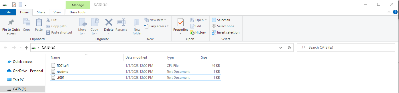
After the flight, connect the board to a computer with a USB-C cable. The flight computer appears as a USB drive containing .cfl flight logs and their associated files. Copy the required files before disconnecting the board, or use the Configurator’s Flight Logs page to browse, view, save, or delete onboard logs.
Visualizing the Flight Data
Open the Configurator’s Flight Logs page and choose or drop a .cfl flight log. The Configurator plots altitude, velocity, acceleration, angular velocity, linear acceleration, pressure, state changes, and actions. Export the data as .csv files for further processing or as an .html file with interactive plots. You can also open the log in CATS Flights. A legacy Python plotting tool is described in Section 9.4 for users who need a customizable local workflow.
Software Updates
Use the Configurator’s Firmware Updates page for normal Vega updates. The complete procedure, including Ground Station and radio-receiver updates, is described in Section 6.
Beeping Patterns
The CATS Vega flight computer uses beeping patterns to indicate its current state or a potential error. The tables below list the available patterns.
| State | Description | Pattern |
| Bootup | The flight computer has booted up. | 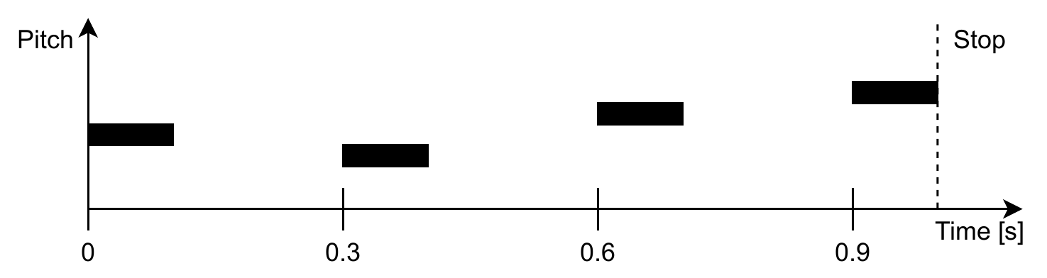 |
| Calibrating Ready | The flight computer has switched from the Calibrating state to the Ready state. | 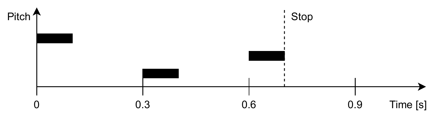 |
| Ready | Calibration was successful, and the flight computer is in the Ready state. | 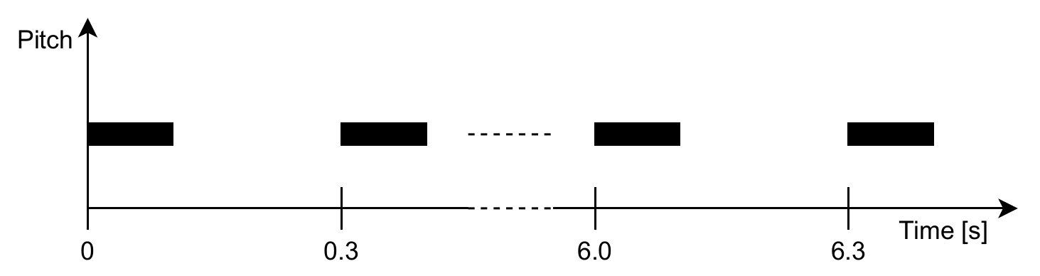 |
| Testing | The flight computer is in testing mode. This pattern sounds only after the computer is rebooted. | 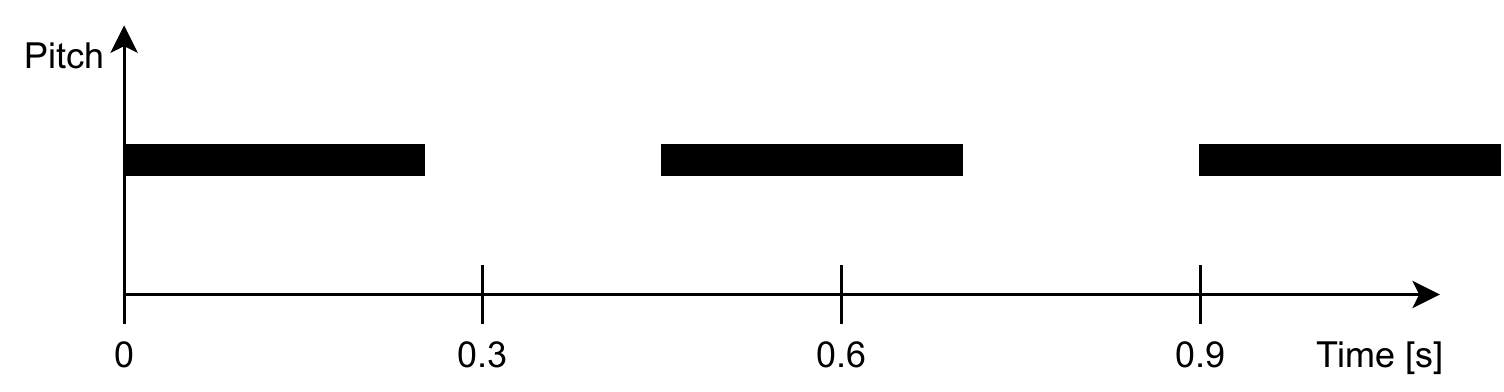 |
| Testing Armed | The flight computer is in the armed testing state. | 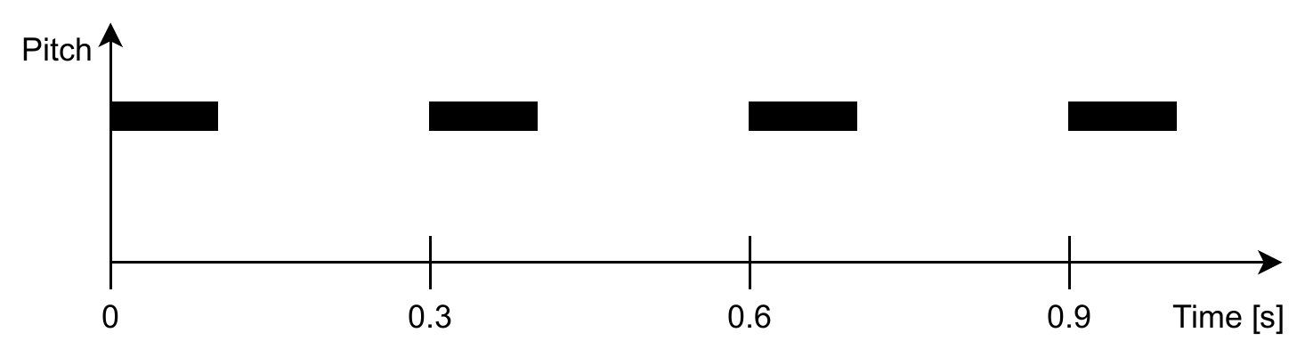 |
Ground Station
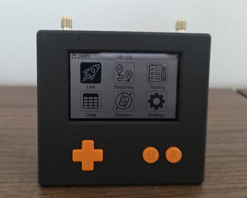
The Ground Station is the counterpart to the CATS Vega. It receives data from the flight computer and sends commands to it. It displays the rocket’s position, velocity, system health, and other important information in real time. This chapter explains how to use the Ground Station and describes its operating principle.
Hardware
Overview
The Ground Station is built around an ESP32-S2 microcontroller and features a transflective display that remains readable in bright sunlight. It has 4 MB of internal flash, including a 1 MB FAT data partition for logs and firmware-transfer files.
Specifications
| Microcontroller | ESP32-S2 |
| Flash Memory | 4 MB internal; 1 MB data partition |
| Battery | Li-Ion 18650 |
| Power Consumption | 60mA |
| Charging Current | 500mA |
| Screen | LS027B7DH01 |
| Radio | 2x SX1280 |
| Radio Range | Tested to 10km @100mW |
| GNSS | ATGM336H-5N |
How to Use
This section covers the basic use of the Ground Station. For more advanced information, refer to the later sections.
Explanation of All Menus
Use the joystick to move left, right, up, and down. Press A to open a menu, select an item, or confirm an action. Press B to go back. Arrows and hints at the edges of the display indicate when another page or action is available.
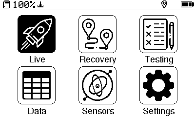
Live
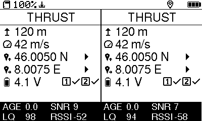
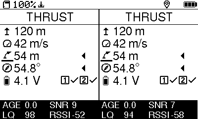
The Live screen shows telemetry from the connected Vega or Vegas. It displays flight state, altitude, vertical velocity, battery voltage, pyro continuity, errors, and radio-link information. Press Left for the GNSS view and Right for the downrange view. The downrange view uses the Ground Station’s own GNSS position to show the rocket’s relative direction and distance.
The link indicators include:
AGE - Time since the last received packet. A link is treated as disconnected after five seconds without a packet.
SNR - Signal-to-noise ratio in dB. Lower values indicate a noisier radio environment.
LQ - Percentage of expected packets received during the recent measurement window.
RSSI - Received signal strength in dBm. More negative values indicate a weaker received signal.
Recovery
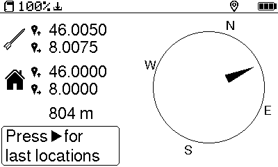
The Recovery screen guides you toward the last valid GNSS position received from the rocket. It shows the selected rocket, distance, relative direction, and whether a usable location is available. Calibrate the Ground Station compass outdoors near the launch site and away from large metal objects before relying on direction guidance.
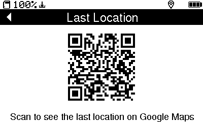
In Dual receiver mode, press Up or Down to choose Link 1 or Link 2. Press Right to show a QR code for the selected last location; scan it with a phone to open the coordinates in a mapping application. If the other link also has a valid location, press Right again to switch QR-code pages. Press Left to return to direction guidance.
Testing
The Testing screen arms testing mode and manually triggers configured flight events. Triggered events execute their assigned actions. Read Section 8 completely before using this screen.
Data
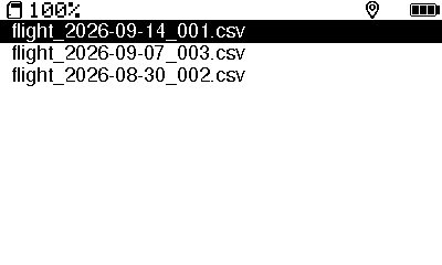
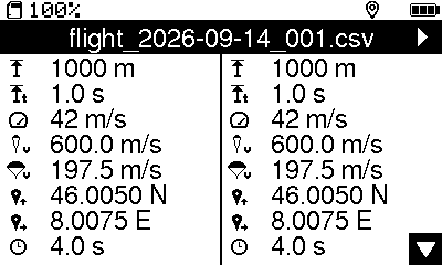
The Data screen lists logs stored on the Ground Station. An active recording is marked as active. Select a log to view its duration, maximum altitude and velocity, flight state, and recorded locations. When a valid location is available, open its QR-code page to transfer the coordinates to a phone.
The options page can finalize the active log or delete a completed log after confirmation. Disconnect the Ground Station USB drive before deleting a log. Finalizing stops the active recording and closes its files; deleting permanently removes the selected completed log.
Sensors
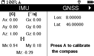
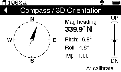
The Sensors screen shows raw IMU, magnetometer, and GNSS readings. Press Right or Down to open the Compass / 3D Orientation page, which shows the Ground Station’s heading, pitch, and roll. Press Left or Up to return to raw readings.
Press A to start compass calibration and follow the on-screen instructions. Rotate the Ground Station slowly through multiple orientations, away from large metal objects and magnets. When calibration reaches 100%, confirm the result to save it.
Settings
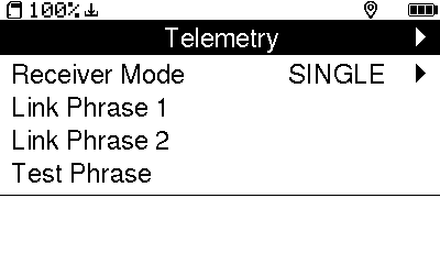
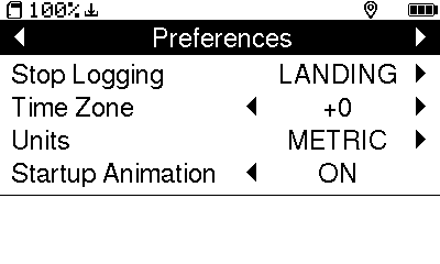
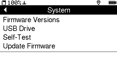
Settings are divided into three pages. Move Left or Right while no setting is selected to change pages.
| Page | Setting | Purpose |
| Telemetry | Receiver Mode | Single uses both receivers for one Vega; Dual assigns one Vega to each receiver. |
| Telemetry | Link Phrase 1 | Phrase used by both receivers in Single mode or the left receiver in Dual mode. |
| Telemetry | Link Phrase 2 | Phrase used by the right receiver in Dual mode. |
| Telemetry | Test Phrase | Phrase required to arm Vega testing mode. |
| Preferences | Stop Logging | Stop at landing or continue until manually finalized. |
| Preferences | Time Zone | Local offset from UTC. |
| Preferences | Units | Metric or imperial display units; recorded data remains metric. |
| Preferences | Startup Animation | Animated startup or static CATS logo. |
| System | Firmware Versions | Ground Station and both receiver-firmware versions. |
| System | USB Drive | View or disconnect the shared USB storage. |
| System | Self-Test | Factory-oriented automatic and guided hardware checks. |
| System | Update Firmware | Update the Ground Station application or both radio receivers. |
Telemetry Modes
The Ground Station’s telemetry settings include a mode option. Because the Ground Station has two receivers, it supports two modes.
In Dual mode, the Ground Station can track two Vega flight computers. This is useful when a section separates from the rocket and you want to track it as well as the main body.
In Single mode, the Ground Station tracks one Vega flight computer. Packets from both receivers are combined, allowing more data to be received than with a single receiver. For best diversity performance, use one directional antenna and one omnidirectional antenna.
Data Streaming via USB
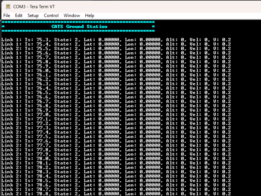
When connected to a computer via USB, the Ground Station continuously streams each newly received telemetry packet through its virtual serial port. Each line identifies the radio link and includes the timestamp, flight state, GPS coordinates, altitude, velocity, and battery voltage; in dual-receiver mode, data from both links is reported.
The serial stream emits one line per newly received telemetry packet. All units are fixed and are not affected by the Ground Station’s unit settings:
Link: Receiving radio link number (1 or 2)
Ts: Flight-computer uptime in seconds, with 0.1 s resolution
State: Numeric flight state (0–7: Invalid, Calibrating, Ready, Thrusting, Coasting, Drogue, Main, Touchdown)
Lat / Lon: GPS coordinates in decimal degrees
Alt: Estimated altitude in meters
Vel: Estimated vertical velocity in meters per second
V: Flight-computer battery voltage in volts, with 0.1 V resolution
Charging
The Ground Station is powered by a Li-ion 18650 battery. A fully charged battery provides more than 8 hours of operation. Charge the battery through the USB port. At a charging current of 500 mA, a full charge can take up to 6 hours. The LED next to the USB port lights while the battery is charging and turns off when charging is complete. To replace the internal battery, remove the battery cover on the back of the Ground Station. If the replacement battery has different specifications, the estimated remaining charge shown on the screen may differ from the actual percentage.
How to Get the Data on Your Computer
When connected by USB and not actively recording, the Ground Station shares its data partition as the CATS GS USB drive. Open the drive and copy the required .csv logs to the computer. The firmware reclaims the filesystem automatically when recording starts and shares it again after the log is finalized. Close files before recording or updating firmware, and use Settings System USB Drive when the drive needs to be disconnected manually.
Software Updates
Use the Configurator’s Firmware Updates page for normal Ground Station and radio-receiver updates. See Section 6 for the complete preparation, installation, verification, and recovery procedures.
Firmware Updates
The Configurator installs official stable firmware for the CATS Vega and Ground Station. It also prepares the firmware file that the Ground Station uses to update both of its radio receivers. Use the Firmware Updates page instead of downloading files and selecting programming tools manually.
Normal firmware installation is supported on Windows. On Linux and macOS, the Configurator can check connected devices and releases, but the standard release keeps flashing disabled until those USB workflows have completed hardware acceptance.
Before Updating
Install the latest Configurator from the Configurator releases page. The Firmware Updates page updates connected CATS devices; it does not update the Configurator application itself.
Save or discard any unsaved configuration changes. Firmware installation is disabled while the Configurator contains unsaved changes.
Connect only the device that you intend to update. Disconnect deployment charges and place the Vega safely on the bench. Stop Ground Station tracking and recording, and close any files opened from its USB drive.
Keep the device powered and connected until the Configurator or Ground Station reports that verification has completed.
Updating the Configurator
Download the current installer from the Configurator releases page, close the running Configurator, and run the installer. After installation, open the Configurator and confirm the expected App version in the footer.
Updating the CATS Vega
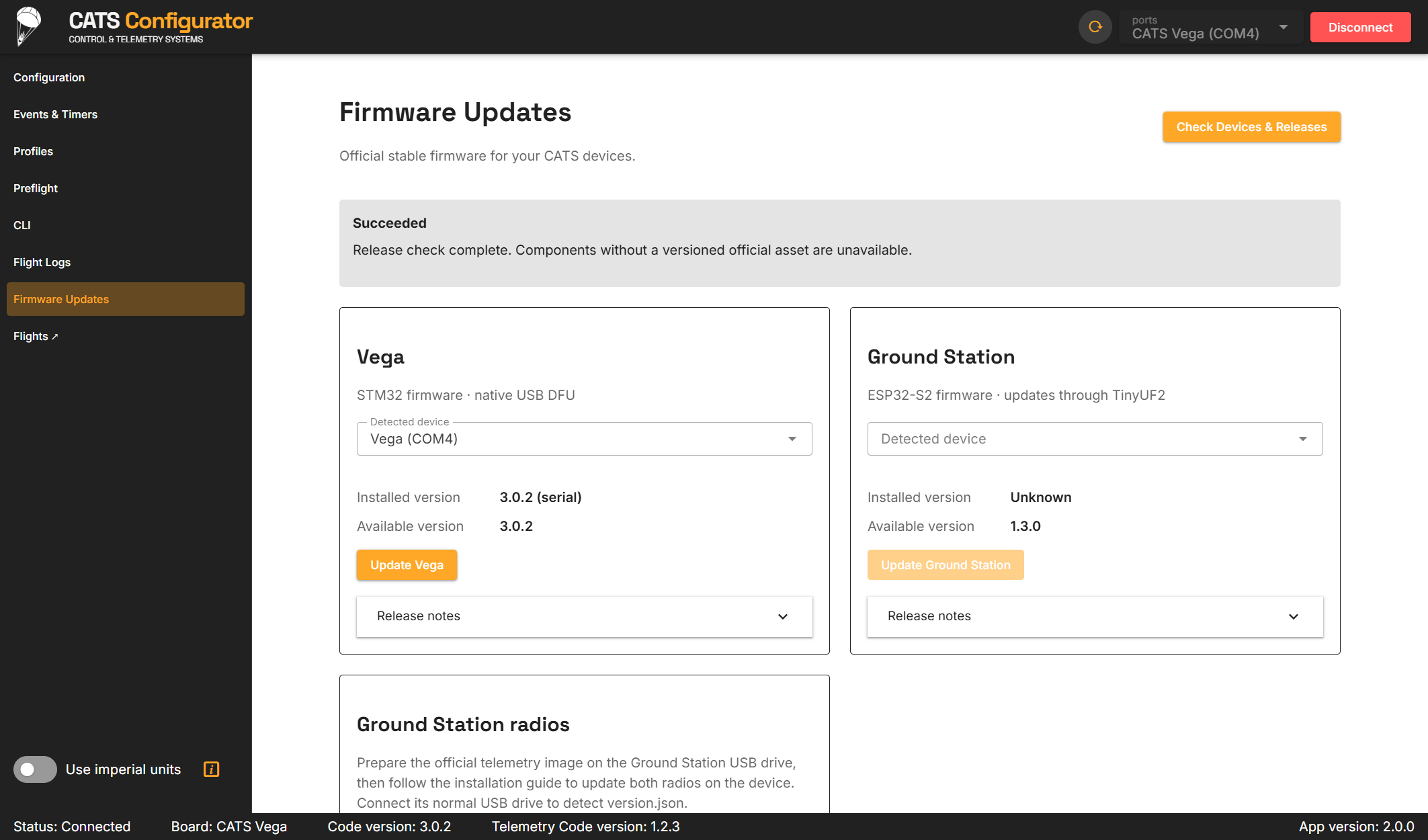
Connect the Vega by USB, open Firmware Updates, and select Check devices & releases.
In the Vega panel, verify the detected device, installed version, and available version. Select Update Vega.
Confirm that deployment charges are disconnected. If the installed version is unknown or the same version is being reinstalled, acknowledge the additional confirmation shown by the Configurator.
Select Start update. The Configurator downloads and validates the official image, moves the Vega into its native USB DFU bootloader, erases and writes the application, reads it back for verification, and starts the new firmware.
Leave USB connected while the Vega reconnects. The update is complete only after the Configurator verifies the running firmware version.
The Configurator prevents cancellation after the device starts transitioning into its bootloader. If the application reports a failed verification or reconnect step, leave the Vega connected and use the offered retry action. STM32CubeProgrammer and an ST-Link debugger are service and recovery tools, not part of the normal update procedure.
Updating the Ground Station
Connect the Ground Station through its normal USB port. Stop tracking and recording, and close all files on the
CATS GSdrive.Open Firmware Updates, select Check devices & releases, and verify the Ground Station detected from its
version.jsoninformation.Select Update Ground Station, confirm the safety prompt, and start the update. Keep the Ground Station connected while the Configurator enters TinyUF2, copies the official
.uf2image, and waits for the application to return.The update is complete only when the Configurator reads a fresh
version.jsonand reports the installed version.
If automatic bootloader entry is unavailable, use Settings System Update Firmware Ground Station on the device. Then return to the Configurator, check devices again, and start or retry the update. Do not use a 1200-baud reset; on this hardware it enters the ESP32 ROM bootloader rather than the supported TinyUF2 update path.
Updating the Ground Station Radio Receivers
The Configurator validates and copies the radio image, while the Ground Station performs the installation on both receiver modules.
Connect the normal
CATS GSUSB drive, open Firmware Updates, and select Check devices & releases.In the Ground Station radios panel, verify the detected drive and available version. Select Prepare radio firmware and confirm that tracking, recording, and file access have stopped.
After preparation succeeds, close all files and safely eject the
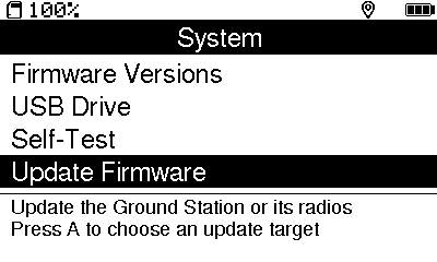
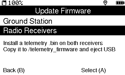
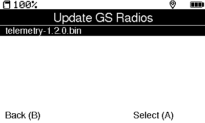
CATS GSdrive from the computer.On the Ground Station, open Settings System Update Firmware Radio Receivers.
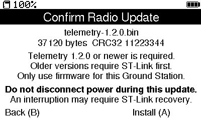
Select the prepared
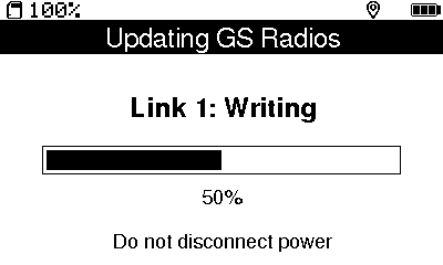
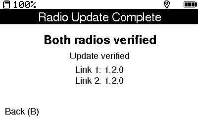
.binfile from thetelemetry_firmwaredirectory and confirm the update. Keep the Ground Station powered while it updates and verifies both radios.Do not leave the update screen until it reports Both radios verified and shows the expected version for Link 1 and Link 2.
Power-cycle the Ground Station, reconnect its normal USB drive, and select Check devices & releases in the Configurator to refresh all reported versions.
The following Ground Station screens show the complete on-device sequence. Filenames, versions, sizes, and checksums are examples; use the file and version prepared by your Configurator.
Recovering an Interrupted Update
Keep the device connected and follow the retry action shown by the Configurator. A Vega that remains in native DFU can be written and verified again. A Ground Station already in TinyUF2 can be checked again before retrying the validated update. If a radio update was interrupted, reopen the Ground Station’s Radio Receivers update screen and run the prepared file again, then verify both reported versions.
If a device cannot enter its supported bootloader or cannot be detected after the documented retries, disconnect all outputs and contact CATS support. Direct programming through STM32CubeProgrammer or an ST-Link debugger is reserved for service recovery and factory provisioning.
Example Configurations
These examples show how hardware, flight events, actions, and timers fit together. Adapt all thresholds, deployment altitudes, delays, and output settings to the actual rocket and recovery system.
Simple Dual-Deployment Example
This example uses a pyrotechnic charge on Pyro Channel 1 for the drogue parachute and a second charge on Pyro Channel 2 for the main parachute.
| Area | Example value | Purpose |
| Configuration | Liftoff threshold: 40 | Detect liftoff after the configured acceleration is sustained. |
| Events & Timers | Apogee → Pyro 1 ON | Deploy the drogue parachute at detected apogee. |
| Events & Timers | Main Deployment → Pyro 2 ON | Deploy the main parachute below the configured main altitude. |
| Events & Timers | Timer: Liftoff → Apogee after 15 s | Provide a time-based backup for the apogee event. |
Connect the battery and switch, then connect the deployment circuits to Pyro Channels 1 and 2 as shown below. Keep the charges disconnected while checking continuity and event behavior.
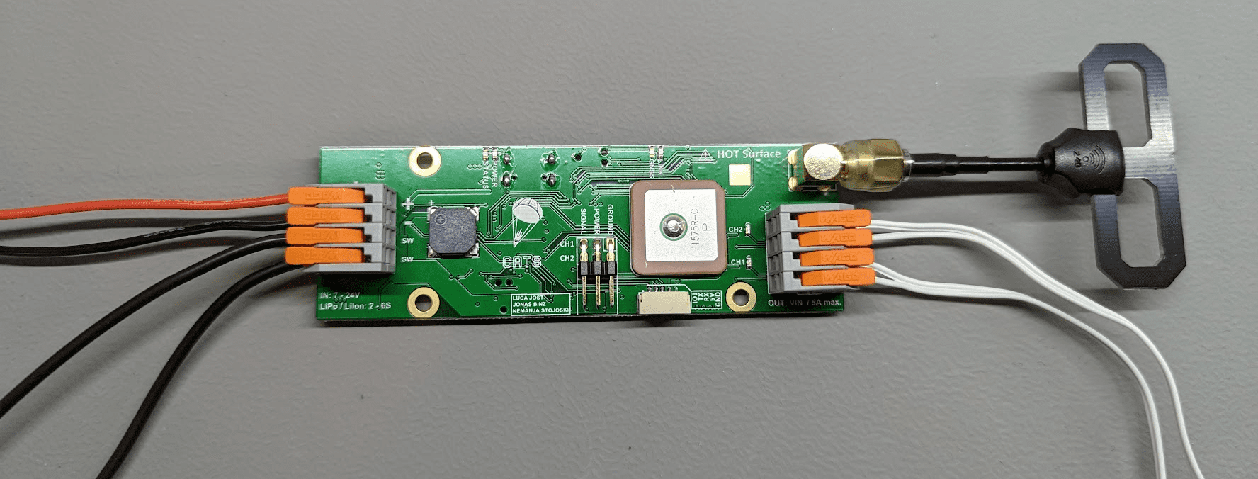
In Preflight, verify the main-deployment altitude, liftoff threshold, timer, event sequence, and both pyro actions. Use the procedure in Chapter 8 to test the configuration with safe substitutes before connecting energetic devices.
Advanced Recovery Example
This example adds timed actions, a servo-deployed main parachute, a camera, and a low-level output. It illustrates the available building blocks; it is not a recommended configuration for a specific vehicle.
| Area | Example value | Purpose |
| Configuration | Liftoff threshold: 40 | Detect liftoff. |
| Configuration | Main altitude: 350 m | Trigger the Main Deployment event below 350 m during descent. |
| Configuration | Servo 1 initial position: mechanism closed | Hold the main-deployment mechanism in its safe initial position. Determine the actual value on the bench. |
| Events & Timers | Apogee → Pyro 1 ON; delay 2 s; Pyro 1 OFF | Operate a solenoid valve for two seconds. |
| Events & Timers | Main Deployment → Servo 1 deployed position | Open the main-deployment mechanism. Determine the deployed value on the bench. |
| Events & Timers | Liftoff → Pyro 2 ON; Touchdown → Pyro 2 OFF | Control an externally powered camera through a suitable interface. |
| Events & Timers | Burnout → I/O ON | Assert the low-level output at burnout. |
| Events & Timers | Timer: Liftoff → Apogee after 45 s | Provide a time-based backup for the apogee event. |
Connect the battery and switch, the solenoid-valve interface to Pyro Channel 1, the camera interface to Pyro Channel 2, and the main-deployment mechanism to Servo Channel 1 as shown below. Observe the electrical limits in Section 4.1 and use external drivers where the load requires them.
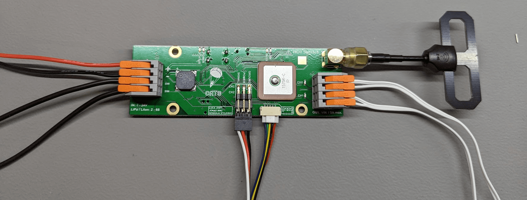
Before flight, use Preflight to inspect the complete timeline, including delayed actions and timer-triggered events. Test each event individually in testing mode, then disable testing mode, reboot the Vega, and run Preflight again.
Testing
Testing mode lets you trigger the Vega’s configured events from a Ground Station while the system is secured on the bench.
What Testing Mode Does
Testing mode stops normal flight-state processing. After the Vega and Ground Station enter armed testing mode, the Ground Station can trigger any configured event. Every action assigned to that event is executed, including pyrotechnic, servo, low-level I/O, recorder, and delayed actions.
Before You Start
Secure the Vega, battery, Ground Station, and every connected mechanism on a suitable test bench.
Disconnect pyrotechnic charges, motors, and other energetic devices unless testing them is the specific purpose of the procedure.
In the Configurator, review Events & Timers and confirm every action that will run for each event.
Open Preflight and resolve every reported configuration or connection problem.
Confirm that the Vega and Ground Station use the same receiver mode, link phrase, and testing phrase.
Enabling and Using Testing Mode
Connect the Vega to the computer and open the Configurator. The Configurator connects automatically when exactly one compatible Vega is available; otherwise, select it manually.
Open Configuration, enable Testing Mode, and set a testing phrase. Save the configuration.
Reboot the Vega. Testing mode does not become active until after the reboot.
Confirm that the Vega emits the Testing beeping pattern described in Section 4.4.
Turn on the Ground Station. In Settings → Telemetry, select the matching receiver mode and set Link Phrase 1 and Test Phrase to the values configured on the Vega.
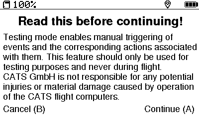
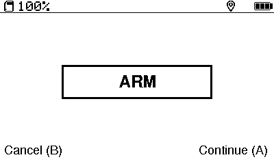
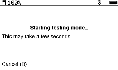
Open Testing on the Ground Station. Read the safety notice, press the A button to continue, and wait for the Ground Station to arm the Vega.
Confirm that the Vega emits the Armed Testing beeping pattern.
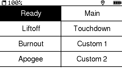
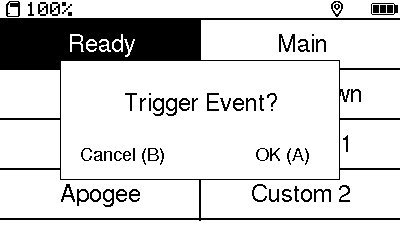
Select an event, review the confirmation screen, and confirm only when the test area is clear. Observe every configured output and delayed action.
Repeat only the checks required for the test. If the telemetry link is lost, return to the Testing menu and arm the system again.
Returning to Flight Configuration
Exit Testing on the Ground Station.
Reconnect the Vega to the Configurator, disable Testing Mode, and save the configuration.
Reboot the Vega and confirm that the Testing beep pattern is no longer emitted.
Run Preflight again before installing energetic devices or preparing the rocket for flight.
Advanced Information
This section explains the core components of the CATS Vega board in greater detail. It is intended for advanced users.
Software Overview
This section provides a brief overview of the software architecture. It is intended for advanced users with some programming experience; understanding it is not required to use the flight computer.
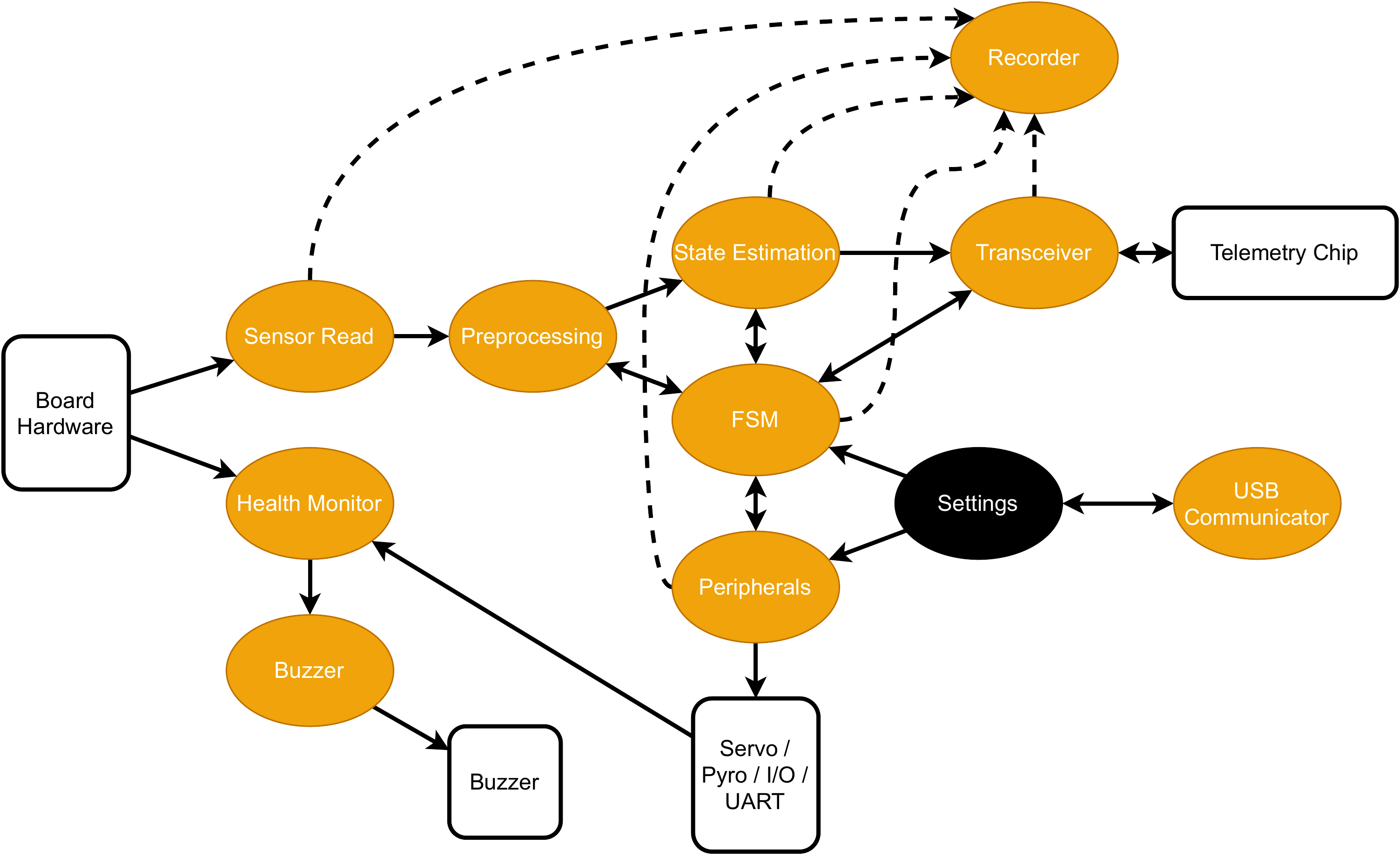
The software is implemented in C++ and uses FreeRTOS as its foundation. The hardware is initialized first, after which the tasks are started. Figure 24 shows the running tasks.
The following list briefly describes each task.
Sensor Read reads the Barometer and IMU data and provides it to the Preprocessing task.
Preprocessing converts the raw barometric pressure to altitude above ground level and the linear acceleration to acceleration in the “up” direction. It provides the processed data to the FSM and State Estimation tasks.
State Estimation estimates the current height and velocity based on the Preprocessing task’s output and the FSM state.
FSM computes the current flight phase from the State Estimation and Preprocessing outputs.
Transceiver handles communication between the main chip and the telemetry chip.
USB Communicator is a group of three tasks that handle the interface between the flight computer and the user’s computer. These tasks do not start when USB is not connected.
Peripherals triggers all user-defined events.
Health Monitor checks values like the buzzer and the battery voltage.
Recorder uses a queue to record all data to the flash chip.
Buzzer actuates the buzzer.
Telemetry
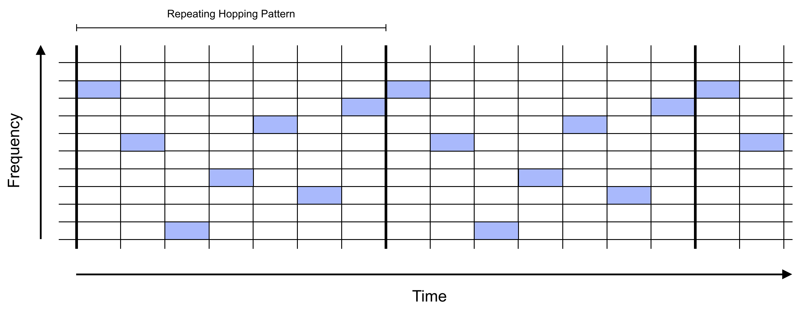
The telemetry system uses 2.4 GHz LoRa and FHSS (Frequency-Hopping Spread Spectrum). FHSS makes transmissions more resistant to interference and more difficult to intercept. It also allows more devices to use the same frequency band with little or no effect on link quality.
Hopping Pattern
The link phrase defines the hopping pattern. It is hashed with a CRC−32 algorithm, and the resulting value seeds a pseudo-random number generator. The generator runs 20 times to define the hopping pattern. As a result, a given link phrase always produces the same pattern. The transmitter and receiver must use the same link phrase to communicate.
Synchronization
The receiver waits on the first frequency until it receives a synchronization packet. This packet contains the link CRC, which identifies the transmission source. If the remote CRC matches the local value, the receiver hops to the next frequency and waits for data. Each data packet contains a checksum for validating its contents. The receiver measures the interval between packets and hops to the next frequency when a packet is not received within the estimated interval. It can perform 30 hops without receiving a packet before synchronization is lost. If the connection is lost, the receiver returns to the first frequency.
Estimation Algorithms
State estimation calculates the rocket’s velocity and altitude from barometric pressure and linear acceleration in the direction.
Calibration of Sensors
Linear acceleration is calibrated when the system enters the Ready state. This allows the flight computer to be mounted in any orientation. The gravity vector is used to calculate the up direction, which is then used throughout the flight.
During Calibrating and Ready, the current altitude above sea level is continuously estimated. Altitude above ground level, the value used during flight, is calculated from the altitude above sea level. This calculation assumes that barometric pressure changes very slowly. When Liftoff is detected, the altitude above sea level is fixed, and only the altitude above ground level is updated.
Kalman Filter
A Kalman Filter estimates altitude and velocity from the calibrated values. Its derivation is described below. We define the state and noise as
where is the altitude above ground level, is the vertical velocity, and is the estimated offset of the measured vertical acceleration. is the noise applied to the vertical acceleration, and is the noise used to estimate the linear-acceleration offset.
The system input is , the linear acceleration measured in the direction.
This is discretized using a first-order approximation:
which gives the system
The process measurement noise matrix becomes
The measurement step assumes that altitude has already been calculated from barometric pressure using the standard barometric formula.
where , C, Pa, is the calibrated altitude above sea level, and is the measurement noise.
The measurement function is
The measurement-noise matrix becomes a scalar:
The standard Kalman-filter equations can then propagate the state.
Gain Scheduling
Gain scheduling reduces reliance on the barometer during high-velocity flight, because barometric measurements can behave unpredictably in the transonic regime.
At Liftoff and while the rocket is moving quickly, the accelerometer is weighted more heavily when estimating altitude and velocity. At lower velocities, barometric pressure is weighted more heavily because accelerometer drift affects the estimate. As the rocket arcs over, the quality of the accelerometer measurement also decreases.
Two variables control the relative trust in the sensors: and . In the algorithm, remains constant, while changes during flight. The conditions for changing are shown below.
where depends on the current velocity.
This gain scheduling effectively filters unexpected barometric measurements at high velocities.
Using the Python Plotting Tool
For more control over flight data, use the legacy Python plotting tool. It provides the Configurator’s plotting functionality in a form that is easier to customize.
To visualize logs recorded by the Vega flight computer, clone the cats-logs repository and run the log_visualizer.py script. Git and Python 3 must be installed to download and run the script.
To visualize your logs, follow these steps:
git clone https://github.com/catsystems/cats-logs.git
cd cats-logs/log_parsing
pip install -r requirements.txt
python log_visualizer.py -i <path to input log> -o <path to output directory>
The script parses the log file and generates a self-contained HTML file containing all plots. It also generates raw and processed CSV files for each type of recorded value.
For more information about the visualizer script, run:
./log_visualizer.py --helpCommon CLI Commands
The CLI is intended for advanced inspection, recovery, and configuration. To access it, connect the Vega through the Configurator and open CLI. The commands and parameters below are the most useful ones; run help for the authoritative list provided by the connected firmware. Square brackets [ ] indicate an optional argument, while angle brackets < > identify a parameter name.
After changing configuration values, run save and verify the result with config.
| bl | Put the board into DFU mode | For advanced recovery. Normal firmware updates use the Configurator workflow in Chapter 6. |
| cd | Change the current working directory | |
| config | Print the flight config in a human-readable format | |
| defaults [–no-outputs] | Reset to default settings | The default configuration triggers pyro channels. If –no-outputs is passed, pyro triggering is not configured. |
| dump | Print configurable settings in a readable format | |
| flash_erase | Erase everything on the flash chip; this might take a while | |
| flash_test | Test writing to and reading from the flash | For testing purposes only; do not use |
| flash_start_write | Start writing to flash | For testing purposes only; do not use |
| flash_stop_write | Stop writing to flash | For testing purposes only; do not use |
| flight_dump <flight_number> | Print a specific flight in binary format | |
| flight_parse <flight_number> | Print a specific flight in a human-readable format | |
| get [command_name] | Get a variable value, described in Table 13 | |
| help [search string] | Display all commands with a description | |
| lfs_format | Reformat the flash filesystem | |
| log_enable | Enable log output on the terminal | |
| ls | List all files in the current working directory | |
| reboot | Reboot the flight computer | This command does not save the changed settings by itself |
| rec_info | Get information about flash usage | |
| rm <file_name> | Remove a file | |
| save | Save flight configuration | |
| set [<command_name>=<value>] | Set a variable, described in Table 13 | |
| stats <flight_number> | Print flight statistics | |
| status | Show current sensor data, flight phase, and other important information | |
| version | Show the firmware version |
Common Configuration Parameters
The variables below can be read with the get command or changed with the set command. Changes are saved to the flight computer’s configuration only after the save command is run.
| acc_threshold | Acceleration threshold above which liftoff is detected | |
| main_altitude | Altitude above ground level under which main deployment is triggered | |
| timer1_start | Event which triggers timer 1 | |
| timer1_trigger | Event which is triggered once timer 1 elapses | |
| timer1_duration | Timer 1 duration | |
| timer2_start | Event which triggers timer 2 | |
| timer2_trigger | Event which is triggered once timer 2 elapses | |
| timer2_duration | Timer 2 duration | |
| timer3_start | Event which triggers timer 3 | |
| timer3_trigger | Event which is triggered once timer 3 elapses | |
| timer3_duration | Timer 3 duration | |
| timer4_start | Event which triggers timer 4 | |
| timer4_trigger | Event which is triggered once timer 4 elapses | |
| timer4_duration | Timer 4 duration | |
| ev_calibrate | Set the actions associated with the calibration event | Do not use! |
| ev_ready | Set the actions associated with the ready event | Do not use! |
| ev_liftoff | Set the actions associated with the liftoff event | Prefer the Configurator’s Events & Timers page. |
| ev_burnout | Set the actions associated with the burnout event | Do not use! |
| ev_apogee | Set the actions associated with the apogee event | Do not use! |
| ev_main_deployment | Set the actions associated with the main deployment event | Do not use! |
| ev_touchdown | Set the actions associated with the touchdown event | Do not use! |
| ev_custom1 | Set the actions associated with the custom 1 event | Do not use! |
| ev_custom2 | Set the actions associated with the custom 2 event | Do not use! |
| servo1_init_pos | Set the initial position of servo 1 | |
| servo2_init_pos | Set the initial position of servo 2 | |
| tele_link_phrase | Set the telemetry link phrase | |
| tele_test_phrase | Set the testing phrase | |
| tele_power_level | Set the telemetry power level | |
| tele_enable | Enable or disable telemetry | |
| tele_adaptive_power | Enable or disable adaptive power for the telemetry power level | Adaptive power mode boosts output power to maximum when the flight computer is in THRUSTING mode and returns it to the user-set value when TOUCHDOWN is registered. |
| buzzer_volume | Set the buzzer volume | |
| battery_type | Set the battery type used with the CATS Vega | |
| rec_elements | Set the desired recorded elements | A bit mask corresponding to the rec_entry_type_e enum |
| rec_speed | Set the desired sampling period for recording | |
| test_mode | Enable or disable testing mode | A reboot is required after saving the change. |
FAQ and Troubleshooting
The Configurator does not find my Vega
Use a USB data cable and connect the Vega directly to the computer. If more than one compatible device is connected, select the intended device manually. Use the refresh button in the device selector after reconnecting the cable. On Windows, also check whether another application has opened the same serial port.
My configuration changes disappear after reconnecting
Select Save before disconnecting or rebooting the Vega. After saving, use Refresh or reconnect and confirm that the stored values match the intended configuration. Run Preflight before flight.
The Ground Station does not receive telemetry
Confirm that telemetry is enabled on the Vega, both devices have antennas attached, and the Ground Station receiver mode and link phrase match the Vega configuration. In Single mode, Link Phrase 1 is used by both receivers; in Dual mode, each receiver has its own phrase. Check the Ground Station’s Firmware Versions page if only one receiver behaves unexpectedly.
Testing mode does not arm
Enable testing mode and set a valid testing phrase in the Configurator, save the configuration, and reboot the Vega. Set the same Test Phrase and receiver mode on the Ground Station. The Vega must emit the Testing beep pattern before the Ground Station can arm it. See Chapter 8 for the complete safety procedure.
A flight or Ground Station log is missing
Vega flight logs can be opened from the Configurator’s Flight Logs page, including logs still stored onboard. Ground Station logs are exposed on the CATS GS USB drive; finalize an active log before copying it, and use Settings → System → USB Drive before disconnecting the cable.
A firmware update was interrupted
Reconnect the device and start the update again using the recovery procedure in Chapter 6. After any update, reconnect and verify the reported version before using the device. Normal Vega firmware installation from the Configurator is supported on Windows.
GNSS position is unavailable or inaccurate
Move the Vega and Ground Station outdoors with a clear view of the sky, keep antennas away from large conductive objects, and allow time for a fix. Do not rely on the last displayed coordinates until the Ground Station shows a current fix.
If the problem remains, collect the device and firmware versions, describe the exact steps taken, and contact us on our Discord server or open an issue in the relevant CATS repository.